Brake LED Troubleshooting
The Toyota OEM service manual has limited detail information.
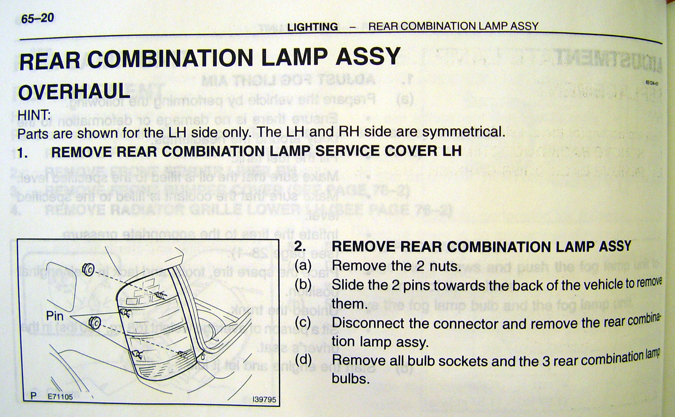
Prius 2004-2005 Tail Brake Light Assembly
Brake LED Troubleshooting
The Toyota OEM service manual has limited detail information.
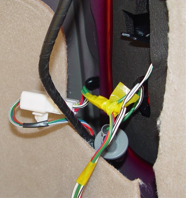
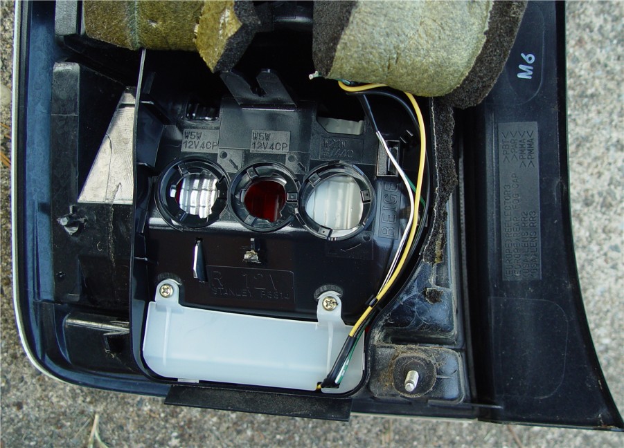
STEP 1) Verify that power is getting to the
assembly.
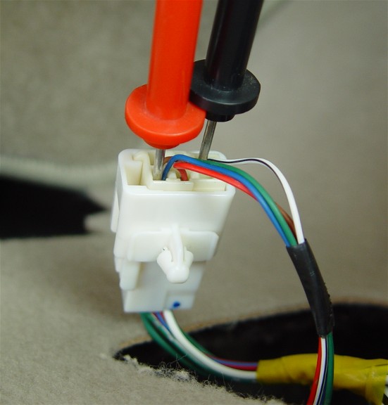
12vdc top of
connector bottom of connector
Start the engine and have someone press the break peddle.
Determine if the driver (LH) side -and/or- passenger (RH) side LEDs are
light.
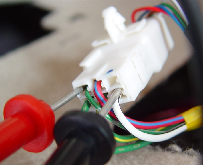
Remove the large center connector and verify 12VDC is coming to the blue wire
(TOP)
and going through the (Bottom) connector on the green wire using the white
wire as ground return.
If you have 12VDC on the green wire leaving the connector, then the trouble is
internal to the assembly.
Proceed to step 2 and remove the assembly for more testing.
STEP 2) Removing the assembly.
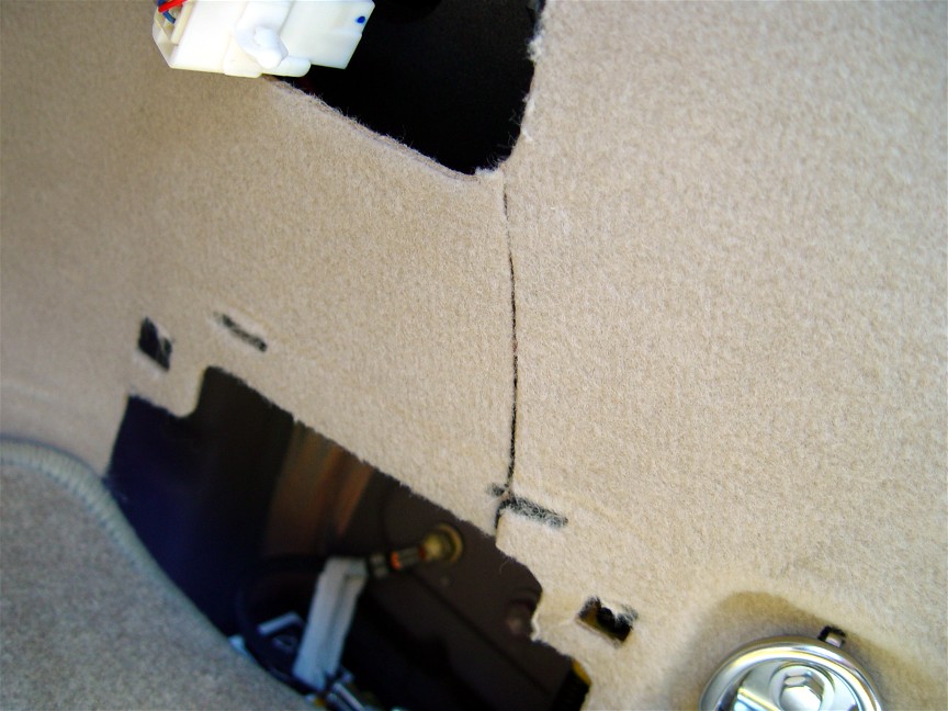
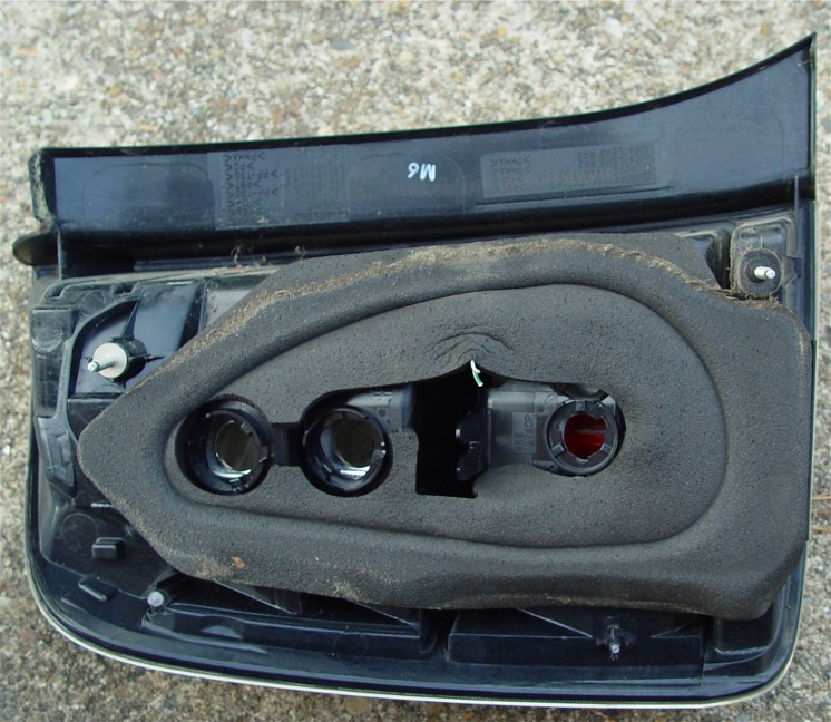
RH passenger side removal. Using a utility knife, cut down to gain
better access. (optional cut)
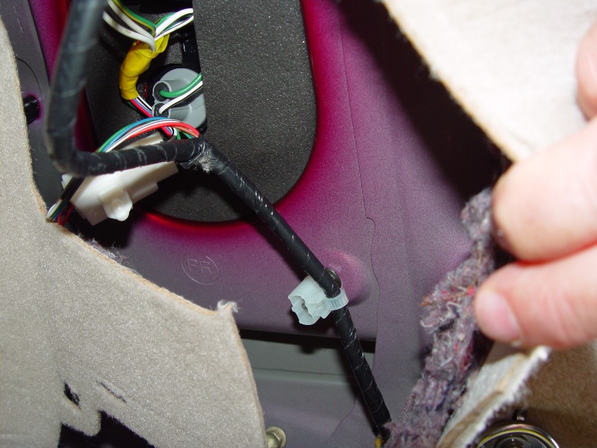
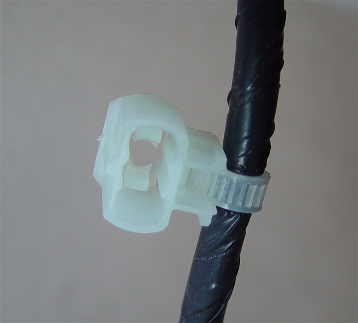
Pull the white cable strap holder off the assemble stud to gain access to the
10mm black nut.
The assembly has a top and bottom stud, each with a white strap holder and 10mm
black nut. Remove both.
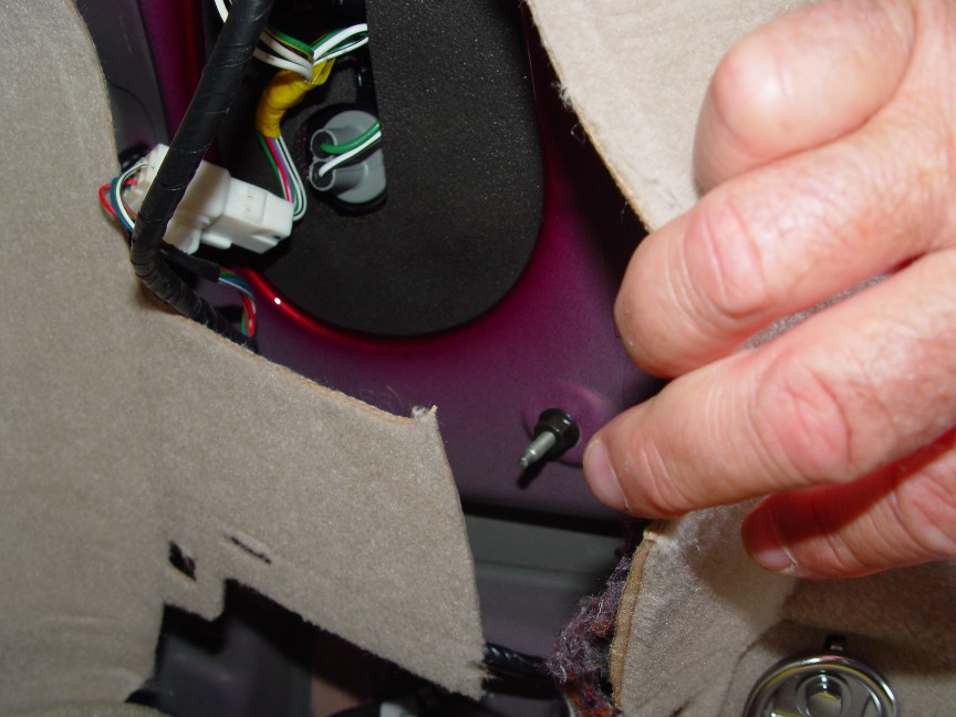
Locate the two black plastic tap keepers (Top/Bottom) toward the body side.
Using a cutter/pliers, break off these two tap keepers.
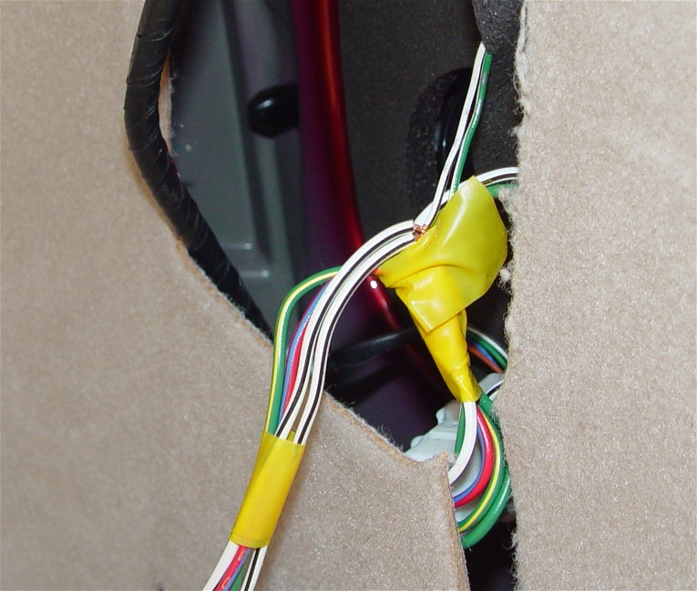
Remove all bulbs, connectors, and cut the green-white wires (mid wire cut) to
free the assembly and remove the assembly.
STEP 3) Remove to inspect and run a quick test on the
resistor/diode circuit board.
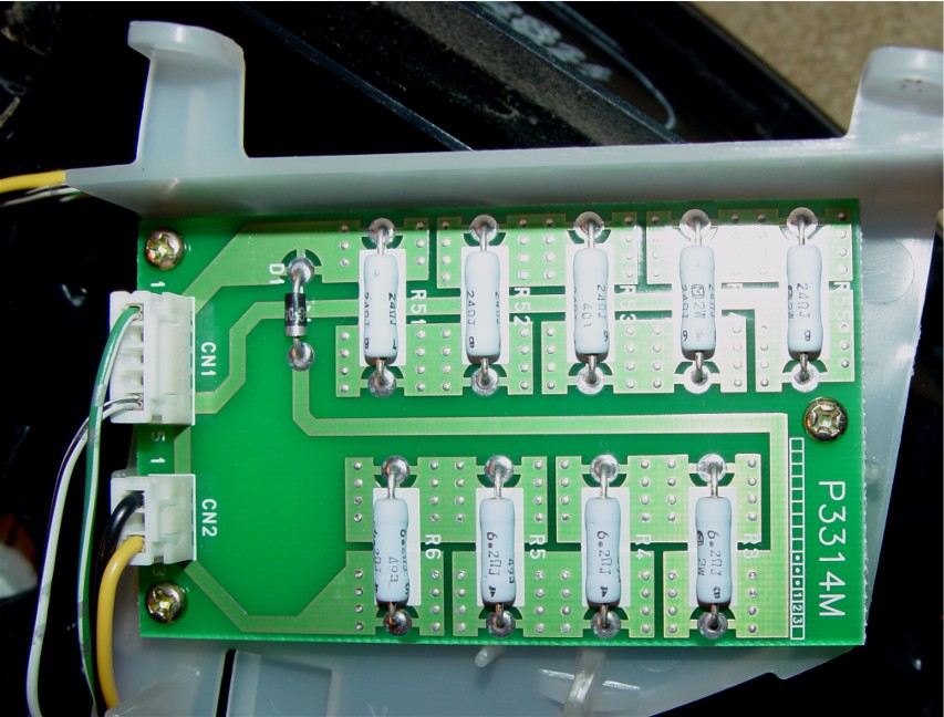
Peel up the bottom side assembly foam and remove the resistor/diode circuit
board (two screws)
The board should be like-new, no burns, broken, or any sign of damage.
Do no try to remove the CN1 or CN2 connectors unless necessary. The pins are
easy to break off.
Removing either the CN1 or CN2 will require pulling the un-used pins out before
reconnecting.
Quick Test of the circuit board.
LED access is very limited at the top of the assembly. More later on
this.
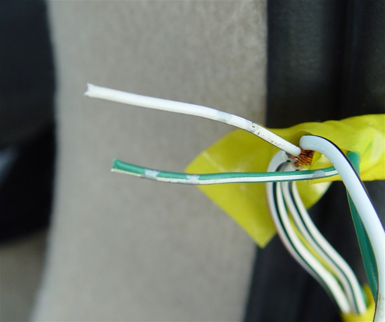
Strip a small portion of the yellow and black wire mid-way up the assembly.
Applying 12VDC to the cut green-white leads you should be able to measure 12VDC
on the yellow black wires.
(+12 on green, -12 on white) ( get +12 on yellow and -12 on black wire)
Applying 12VDC to the cut green-white leads should light the LEDs if the
assembly is working correctly.
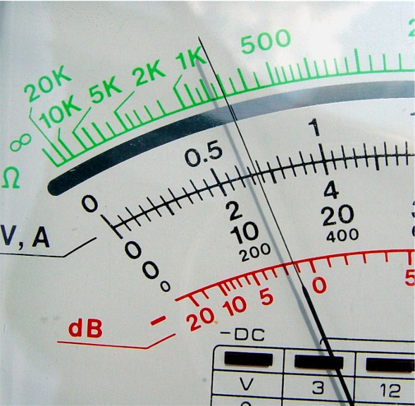
To fully test the circuit board, collect a small test light across the yellow
and black leads.
The circuit board is capable of supplying 400 ma, about 1/2 amp to the test
light (or LEDs for that matter).
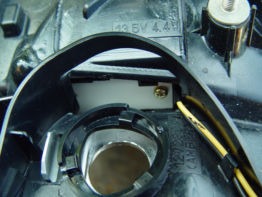
STEP 4) LED access.
Copyright © 2010 www.curtis.anderson.name All rights reserved.
_